Each dataset captured by a drone is not just a collection of images or point measurements. It is a direct projection of the GNSS-derived trajectory into geometric space.
When positioning is stable, the structure of the data remains predictable. When it degrades, the effects appear as geometric distortions: shifts, discontinuities, and local inconsistencies.
These effects are especially visible in LiDAR and photogrammetry, where every positional error is propagated directly into the final model.
This article focuses on how GNSS degradation translates into visible artifacts in point clouds and orthomosaics, and how these patterns relate to specific failure modes in positioning.
Even with enough satellites, poor geometry reduces positional stability. High PDOP does not create random noise — it produces systematic spatial distortion.
This typically occurs in constrained environments such as valleys or mountainous areas, where satellite visibility is limited. In such conditions, RTK initialization may be slow, unstable, or fail entirely, leading to degraded positioning in parts of the dataset
Multipath occurs when GNSS signals reflect off nearby surfaces before reaching the receiver. It is most common in urban or industrial environments with dense structures.
Reflections from buildings and ground surfaces introduce positional errors that can reach tens of centimeters even under RTK. These errors are spatially inconsistent and usually become visible only in processed data.
More detailed analysis of GNSS challenges in environments with glass façades and steel structures is covered in the article The Problem of Drone Mapping in Glass-and-Steel Cities
RTK performance can degrade due to signal obstruction or loss of communication with the base station. In larger sites, this often happens when the rover exceeds reliable correction range.
When this occurs, the system switches between FIX, FLOAT, and standalone modes. The result is a dataset with mixed accuracy levels, where different segments are captured under different positioning quality.
GNSS errors directly affect:
Once incorrect positions are recorded, every downstream product inherits that error.
Flat surfaces appear as volumetric bands rather than clean planes. This effect is typically subtle at first glance, but becomes obvious in structured areas such as roads, roofs, or paved industrial sites.
This type of distortion is usually associated with small but continuous trajectory instability during data acquisition. GNSS does not fail abruptly in these cases — instead, positioning accuracy fluctuates slightly over time, introducing cumulative geometric noise.
Typical conditions where this appears:
What is happening in the data:
Instead of a single stable plane, each scan line or image strip is slightly shifted relative to the previous one. These small offsets accumulate across the flight path, resulting in a “thickened” surface.
Objects appear duplicated with a visible offset between layers. This is one of the most recognizable GNSS-related artifacts in LiDAR.
Unlike gradual blurring, ghosting is usually caused by short-term but more abrupt positioning shifts.
Typical conditions where this appears:
What is happening in the data:
A portion of the dataset is recorded under one stable GNSS solution, while another portion is captured under a slightly shifted solution. The transition is not always smooth, resulting in duplicated geometry.
In urban environments, this often appears along building edges or vertical structures, where reflections are strongest and positional ambiguity is highest.
The dataset is internally consistent — geometry is clean, shapes are preserved — but the entire model is shifted relative to ground truth or control points.
Typical conditions where this appears:
What is happening in the data:
In practice, this often manifests as a constant shift of the full point cloud or orthomosaic relative to GCPs — without internal deformation.
Ground control points do not align with the orthomosaic.
This occurs when the entire dataset inherits a consistent positional bias from GNSS or base station errors. Field cases show that even correctly executed workflows can produce offsets of tens of centimeters when multipath effects or poor satellite geometry persist during acquisition. In such situations, the internal geometry remains coherent, but the dataset is shifted relative to the true coordinate frame defined by GCPs.
GNSS-induced distortions in drone data cannot be eliminated by a single measure. Their mitigation depends on how many layers of the positioning pipeline remain stable — from signal acquisition to final reconstruction.
In practice, robustness is built progressively. Each level reduces the probability or impact of artifacts such as drift, ghosting, or dataset offset.
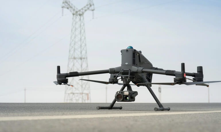
The first and most important factor is the stability of the trajectory at the moment of data capture.
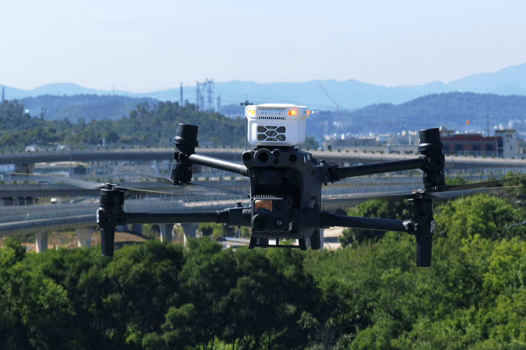
Modern platforms such as DJI Matrice 400 paired with DJI Zenmuse L3 improve baseline stability by reducing sensitivity to minor GNSS fluctuations and maintaining more consistent sensor geometry during flight.
What this mitigates:
At this level, most errors are reduced at the source rather than corrected later.
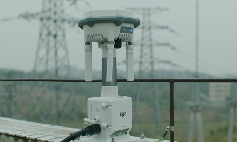
The second layer focuses on improving the quality and stability of the GNSS correction solution.
Reliable RTK corrections depend on the quality of the reference station setup, communication link stability, and satellite visibility. A properly configured local base station or network RTK service helps maintain consistent positioning throughout data acquisition.
What this mitigates:
Additional field practices:
This layer ensures that errors remain bounded rather than propagating across the entire dataset.
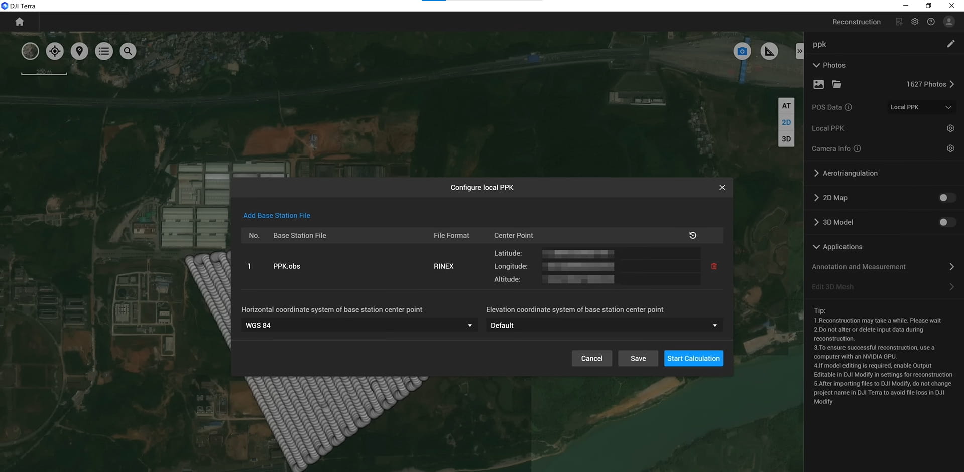
When GNSS degradation cannot be fully prevented during acquisition, part of the error can be compensated during processing.
Software such as DJI Terra can use image-based positioning and reconstruction techniques to partially correct trajectory inconsistencies.
What this mitigates:
Important limitation:
This layer cannot fully recover structural integrity if:
Processing can refine geometry, but it cannot reconstruct missing positional certainty.
The final and most reliable layer is external validation using ground control points (GCPs).
What this mitigates:
GCPs do not prevent GNSS errors — they expose them.
GNSS-related issues do not appear directly during data acquisition. They become visible later through consistent patterns in the final outputs:
These patterns are not random. Each of them corresponds to a specific failure mode — multipath effects, weak satellite geometry, or loss of correction data.
The key point is that these issues are not inherently unavoidable. They are well-understood and can be mitigated through proper system design, field practices, and validation workflows. In most cases, data quality is defined less by the presence of errors and more by how early they are identified and controlled.
Understanding how GNSS degradation translates into point cloud and orthomosaic artifacts allows teams not only to diagnose problems, but to prevent them through the right combination of equipment, configuration, and verification steps.
Accurate mapping is therefore not only a matter of sensors or software, but of managing positioning stability across the entire workflow — from acquisition to final validation.