Illegal parking patrols usually require an operator to watch a live feed, identify a stationary vehicle, confirm its position and manually collect evidence. With DJI Matrice 400, Manifold 3 and a compatible H30 series camera, much of this workflow can be automated.
This tutorial explains how structured prompts can guide an AI through the development of a complete illegal parking detection application.
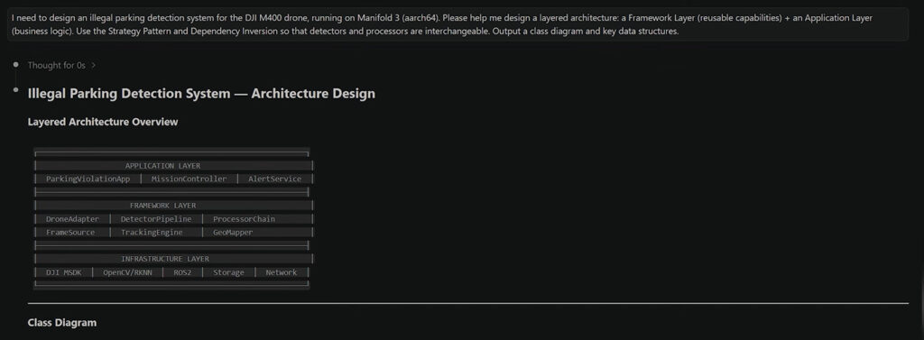
The system is divided into two layers. The Framework Layer provides reusable interfaces and services: TargetDetector, TargetProcessorBase, flight and camera control, video transmission, and metadata conversion. The Application Layer contains the illegal parking logic, including patrol monitoring, T0/T1 vehicle matching, GPS deduplication, and evidence collection.
Concrete components such as the YOLOv5 detector and VehicleForensicsProcessor implement the framework interfaces and are passed to the application as interchangeable strategies. This allows the detection model or evidence-processing workflow to be replaced without changing TrafficMonitor or the main patrol logic.
Prompt example
“I need to design an illegal parking detection system for the DJI M400 drone, running on Manifold 3 (aarch64). Please help me design a layered architecture: a Framework Layer (reusable capabilities) + an Application Layer (business logic). Use the Strategy Pattern and Dependency Inversion so that detectors and processors are interchangeable. Output a class diagram and key data structures.”
This prompt establishes the system boundaries before implementation begins. It also asks the AI to define the class relationships and shared data structures that later modules will use.
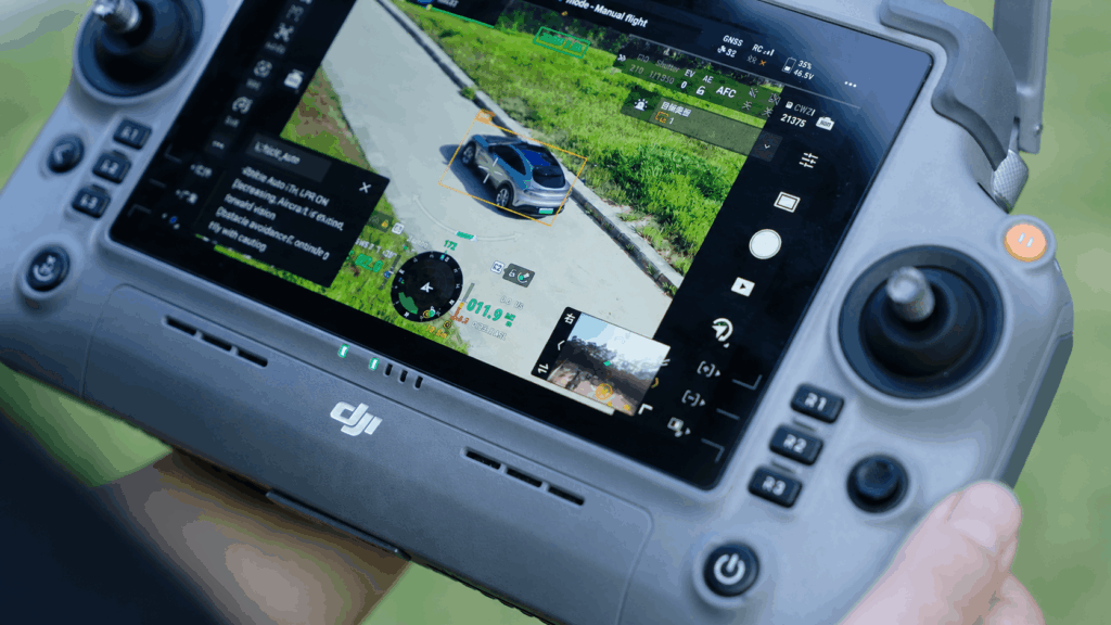
Once the architecture is defined, the first operational module is the vehicle detector. In this setup, YOLOv5 runs through TensorRT on Manifold 3 and uses a VisDrone model suited to aerial imagery. The detector filters the model output so that only relevant vehicles—cars, vans and trucks—continue through the pipeline.
License plate recognition is treated differently from general vehicle detection. It remains disabled during routine patrols to preserve computing resources and is activated only when the application begins collecting evidence. Recognition results are validated before they are stored, while screenshot limits prevent the system from creating an uncontrolled number of files for the same plate.
The detector must also translate its output into the normalized coordinate system used for overlay boxes in DJI Pilot 2. That allows operators to see the YOLO detections directly in the flight interface.
Prompt example
“Please implement a vehicle detector that inherits from the TargetDetector Base interface. Requirements:
This prompt defines the concrete vehicle detector, including YOLOv5 inference, class filtering, optional license plate recognition, screenshot management and conversion of results for the DJI Pilot overlay.
Detecting a vehicle in one video frame does not prove that it is parked. The application needs to observe it over time and distinguish a stationary target from a vehicle moving slowly through the scene.
The proposed TrafficMonitor uses a two-frame comparison. When a vehicle appears, the route is paused and the drone is given two seconds to stabilize. The system captures the first observation, T0, waits for a configurable interval and then captures T1. It matches vehicles across the two frames and measures their displacement in pixels.
Matching begins with vehicles of the same type. If no suitable match is found, the system performs a second pass across different vehicle types. This fallback matters because an aerial detector may label the same vehicle differently as its angle, scale or visibility changes. An exclusive matching constraint prevents a single T1 detection from being assigned to several T0 vehicles.
If the nearest matched position is within the configured displacement threshold, the vehicle is treated as parked. GPS-based deduplication then checks whether it has already been documented nearby.
Prompt example
“Implement the illegal parking detection logic TrafficMonitor:
This prompt implements the T0/T1 comparison, uses pixel displacement to classify stationary vehicles and adds GPS deduplication so the same target is not processed repeatedly.
After a parked vehicle has been confirmed, the drone needs to collect usable evidence without leaving the aircraft or camera in an incorrect state. The forensics processor divides that procedure into four phases.
First, the system retrieves the drone’s current fused position, calculates an appropriate stopping point and flies toward the target. It then adjusts the gimbal, selects the zoom camera, sets the required zoom level and enables license plate recognition. During evidence capture, the drone performs a Point-of-Interest orbit, records video and uses the loudspeaker to issue a warning. Finally, the system disables recognition and returns the camera and gimbal to their patrol settings.
Cleanup is a critical part of this workflow. A failure during camera configuration or the POI mission should still trigger the reset phase. Otherwise, the drone may return to patrol with an incorrect zoom level, gimbal angle or recognition state.
Prompt example
“Implement the forensics processor VehicleForensicsProcessor, inheriting from TargetProcessorBase, with 4 phases:
Key requirement: If Phase B or C fails, Phase D must be called automatically to clean up device state and prevent the gimbal/zoom from getting stuck in the forensics configuration.”
This prompt produces the complete evidence-collection strategy: approach the target, configure the payload, execute an orbit and restore the equipment state even when an intermediate operation fails.
The application needs reliable target coordinates before it can approach a parked vehicle. Tap Zoom aligns the camera with the vehicle, after which the H30 series laser rangefinder can provide positioning data.
SDK output should never be accepted without validation. A zero distance can be recorded as a warning without stopping the overall workflow, but near-zero or out-of-range coordinates must be rejected. Invalid targets are skipped immediately so one failed ranging attempt does not block patrol activity.
Prompt example
“Implement the GetTargetPosition method:
This prompt combines Tap Zoom alignment with laser positioning and three levels of validation. The result protects the flight workflow from unusable target coordinates.
Operational values will need adjustment during field testing. Flight speed, observation time, pixel-displacement tolerance, deduplication radius, zoom level, orbit duration and other parameters should therefore live in a JSON configuration file rather than in compiled code.
A ConfigLoader singleton provides consistent access to these values across the application. Meanwhile, mutexes protect shared resources and condition variables notify the relevant tasks when the system changes state.
The deployment workflow can then synchronize the source to Manifold 3, compile the native application, generate the DPK and install it. Version values must match in both required files before compilation.
Prompt example
“Design a JSON configuration file so that all operational parameters can be modified at runtime without recompilation. Use cJSON for parsing, with a ConfigLoader singleton providing global access. Design a multi-threaded cooperation model: protect shared resources with mutex locks, and use condition variables to notify state changes. For compilation and deployment, use rsync to sync source code to Manifold 3, cmake for native compilation to generate a DPK package, and install via dji_app_ctl. Version numbers must be updated in both app. json (firmware_version) and application.cpp (debugVersion) consistently.”
This prompt moves 17 tunable parameters into runtime configuration, defines coordination between six concurrent tasks and establishes the path from synchronized source code to an installed DPK. The AI should finish by listing every modified file and deliverable so the build can be verified.
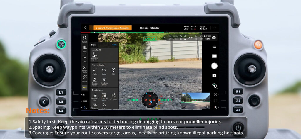
Before launching the application, confirm that Manifold 3, DJI Matrice 400 and the H30 series zoom camera are connected correctly. Their status should be visible in the DJI Pilot 2 flight interface.
Open the customizable function bar and launch the relevant DPK. Select Routes, choose Create Route, and then open Waypoint Route. Add waypoints on the map to cover the patrol area.
A flight speed of 2 m/s is recommended as a starting point. Higher speeds can introduce motion blur into the frames used for detection and matching. The takeoff altitude and camera angle should also be adjusted for the site so vehicles remain clearly visible to the YOLO model while the aircraft maintains a safe operating height.
When the route is ready, tap the save icon and then the perform icon to open the pre-flight check screen. Review the aircraft, payload, route and application status. If all checks pass, upload the flight mission and start the patrol.
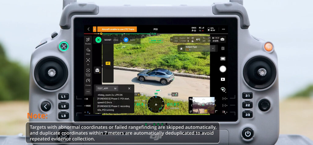
In patrol mode, YOLO bounding boxes appear in the DJI Pilot 2 view, confirming that inference and video metadata transmission are working. When the application identifies a possible stationary vehicle, it pauses the route and performs the T0/T1 comparison.
If the vehicle meets the parking criteria and has not already been documented, the drone aligns the camera using Tap Zoom and requests its position from the laser rangefinder. It then approaches the target, changes the gimbal and zoom settings, enables OCR and attempts to read the license plate. The drone performs a POI orbit while capturing evidence and issuing the configured loudspeaker warning.
After the evidence sequence, the application restores the patrol camera settings and continues the route. Photos and recognition screenshots are stored on Manifold 3 for later review.
Check the log at /open_app/M400-parking-monitor/data/logs/latest.log. Common causes are an incorrect config.json path or invalid PSDK credentials.
Confirm that the video transmission is properly connected and that no DJILiveview initialization errors appear in the application log.
Check whether the stopped_pixel_threshold parameter is too small, or whether the vehicle drove away within observation_interval_sec.
Confirm that the target is within the laser’s effective ranging distance (approximately 1,200 meters for the H30). Vehicles with failed rangefinding are skipped automatically and recorded in the log.
Modify firmware_version in app.json and debugVersion in application.cpp, keep the two values consistent, then recompile.
Confirm that the zoom level and gimbal angle are appropriate and that the ROI is no smaller than 30×20 pixels. Screenshots are not saved when the recognition confidence is below 0.8 or fewer than 5 characters are recognized.