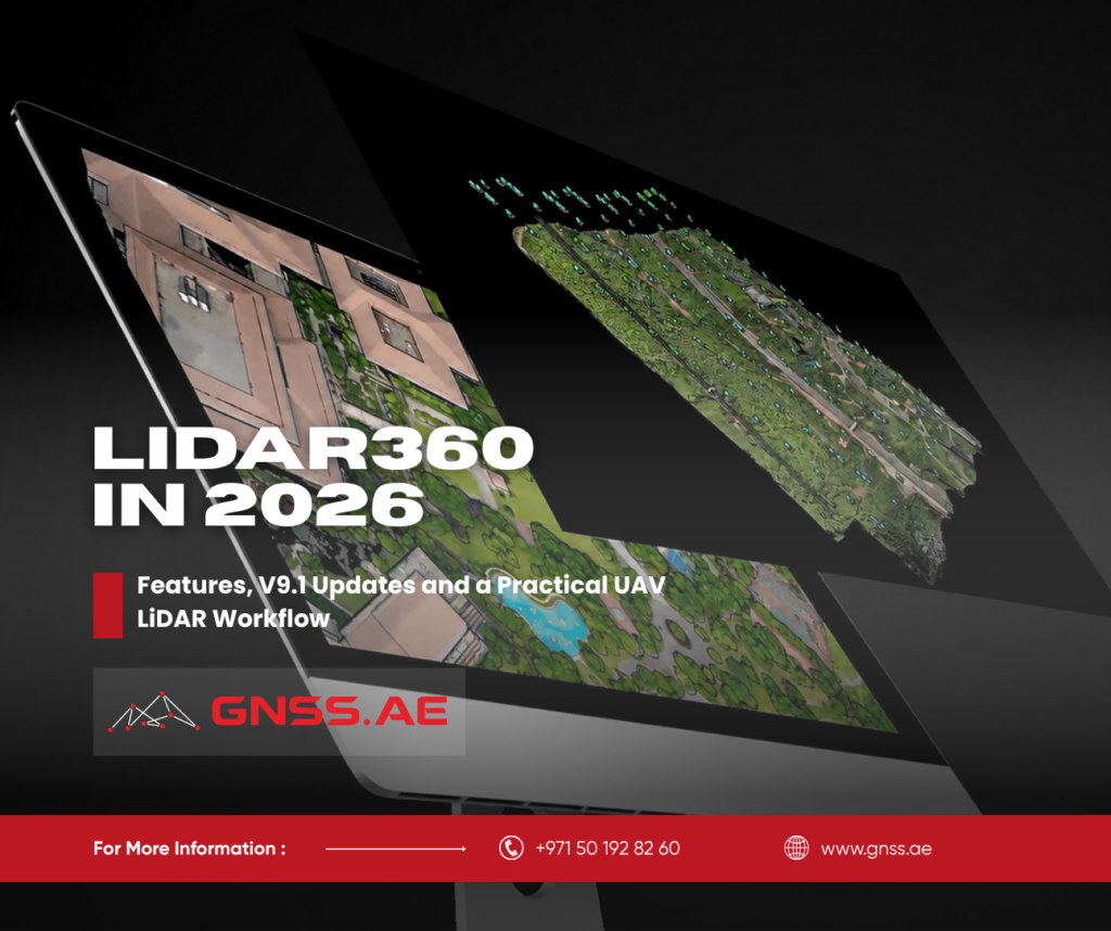
A LiDAR survey does not finish when the scanner produces a point cloud. The raw data still needs to be checked, aligned, classified and converted into something that can be used in a survey, engineering or asset-management project.
LiDAR360 is the software layer that handles this work. Developed by GreenValley International, it processes LiDAR point clouds, imagery and related spatial data.
In this article, we look at what LiDAR360 is used for, the outputs it can produce, the main changes introduced in V9.1.0 and the workflow for turning UAV LiDAR data into verified survey deliverables.
LiDAR360 is desktop point cloud processing and analysis software. It works with data collected from UAV, airborne, terrestrial and other laser-scanning platforms, as well as photogrammetric and spectral data.
The software is modular. A survey company can begin with the Framework and add specialized modules for terrain, forestry, mining, imagery, 3D buildings or distributed processing.
The official LiDAR360 V9 package currently includes:
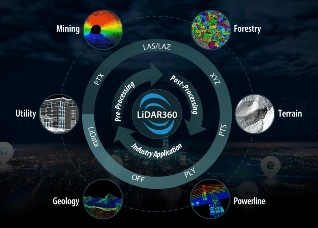
The Framework covers common operations such as point cloud management, registration, strip alignment, classification, measurements, format conversion and quality inspection. Industry modules add workflows and calculations for particular types of projects.
LiDAR360 supports standard formats such as LAS, LAZ, E57, PLY, PCD, CSV and XYZ. It can also work with raster, vector and model data. Results can be exported for use in GIS, CAD and engineering software.
The result depends on the data and the module being used.
Project | LiDAR360 operation | Typical result |
Topographic survey | Ground classification and terrain generation | Ground point cloud, DEM, DSM, contours, slope and aspect maps |
UAV LiDAR quality control | Trajectory, strip, control-point and density checks | Accuracy tables, flight records and QC report |
Construction or mining | Surface reconstruction and volume analysis | Stockpile volume, cut-and-fill calculations and change reports |
Road or tunnel survey | Section extraction and comparison | Cross-sections, longitudinal profiles, deformation or overbreak reports |
Forestry | Tree segmentation and attribute extraction | Tree locations, height, DBH, crown size and estimated volume |
Hydrology | Terrain-based flow analysis | Flow direction, accumulation, channel networks and flood areas |
Urban modelling | Building extraction and modelling | Building footprints, attributes and textured 3D models |
Photogrammetry | Image alignment and surface generation | Point clouds, orthophotos, textured meshes and image reports |
Separate UAV flight strips may contain small differences caused by GNSS/IMU errors, sensor mounting angles or trajectory processing. They often become visible on roofs, roads and other hard surfaces in overlapping areas.
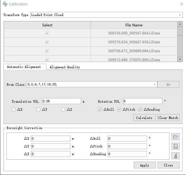
The Strip Alignment tools use overlapping geometry to estimate and correct these differences. The operator can load trajectories, match them with the point cloud, calculate boresight corrections and preview the alignment in a profile window before writing the corrected point cloud.
LiDAR360 includes several ground-extraction methods, including progressive filtering, CSF filtering and deep-learning classification.
The Classify Ground by Deep Learning function was introduced with V9. GreenValley reports accuracy above 94% for its AI ground-classification workflow, including tests involving slopes and vegetation.
After automatic classification, users can inspect the result in Profile View and move incorrectly classified points between classes.
LiDAR360 V9 added a visual Model Builder that combines more than 200 tools into reusable processing models.
The operator places tools on a canvas, connects inputs and outputs, sets parameters and saves the workflow. A saved model can be applied to similar datasets without rebuilding the process each time. Model files can also be called through batch processing or distributed across multiple computing nodes.
A practical model might include:
Model Builder is opened from the geoprocessing tools. Data and processing tools are dragged from the directory tree to the main canvas, connected and then run as a single workflow.
Automatic terrain generation usually requires some correction around buildings, bridges, retaining walls, water bodies and sharp changes in elevation.
LiDAR360 provides tools for adding breaklines, flattening selected areas, smoothing elevations and removing spikes or holes. V9 also added automatic joining of fragmented contour and breakline sheets.
Sections can be exported to PDF and LandXML/J-LandXML, making the results easier to transfer into road, civil-design and machine-control workflows.
For stockpiles and earthworks, LiDAR360 creates a surface from the point cloud and compares it with a reference plane or another surface.
The software can calculate:
The V9.1 update expanded the Volume Measurement function with calculations for pile density, weight, void volume and surface area. These additions allow the same survey result to support both geometric measurement and material reporting.
GreenValley released LiDAR360 V9.1.0 on 30 January 2026.
The update concentrates on practical improvements to accuracy checking, terrain sections, forestry analysis, distributed processing and volume measurement.
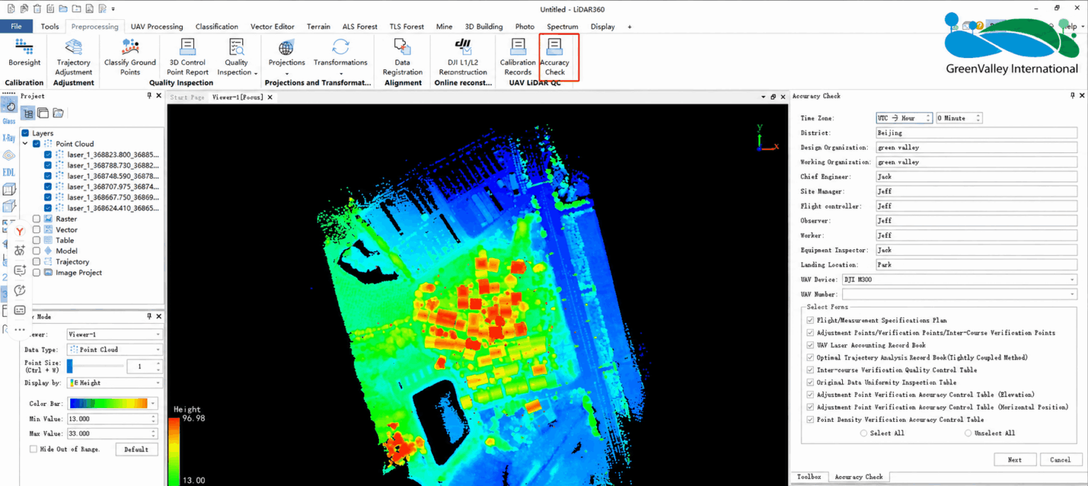
For LiGeo projects upgraded with the newer calibration files, Accuracy Check can now populate relevant project data automatically. This reduces repeated manual entry when preparing calibration and accuracy documentation.
Section Analysis received two important additions:
These functions are useful for road corridors, channels, pipelines and other linear projects where the team needs more than a single centerline profile.
V9.1 added:
GreenValley also reports a 50% efficiency improvement in the Individual Tree Statistics tool and changes to the Individual Tree Crown Segmentation results.
The updated tool can include pile density, estimated weight, void volume and surface area. This is useful where a stockpile report needs to show both volume and an estimated material quantity.
LiDAR360 V9.1 can automatically detect available compute nodes. This simplifies the setup of distributed processing for large datasets and saved Model Builder workflows.
The update also added:
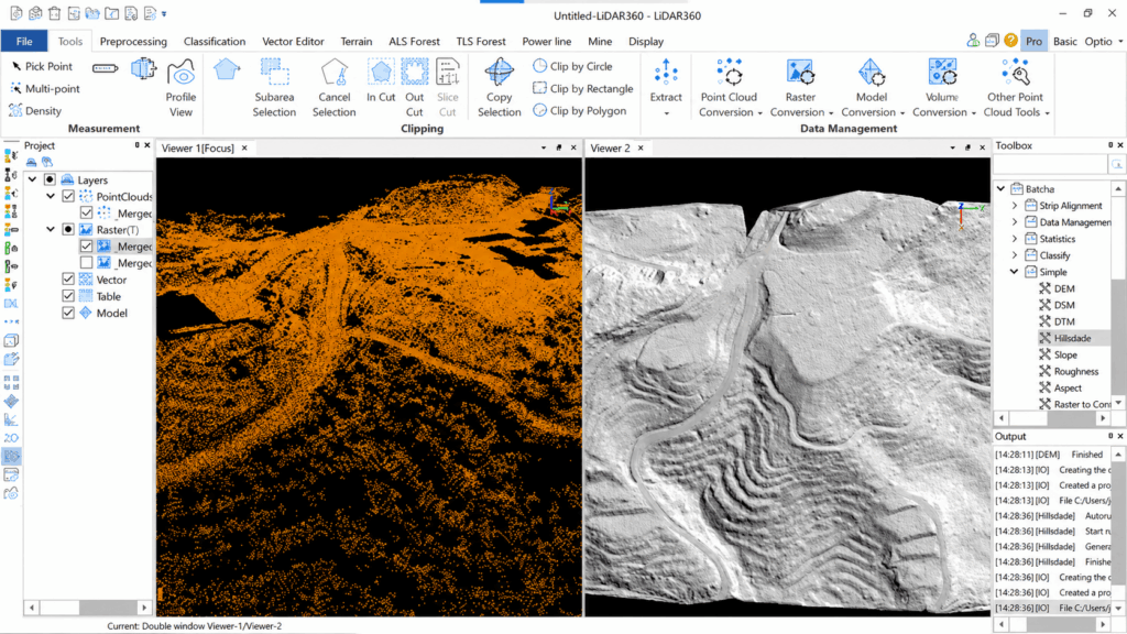
A typical LiDAR360 workflow moves through three main tasks: checking the source data, confirming its accuracy and producing the required survey outputs. The exact settings depend on the sensor and project specification, but the following sequence covers the main stages of a UAV LiDAR project.
Most of the required information can be prepared before processing begins.
Required input | What it contains | Why it is needed |
LiGeo project | Processed trajectory, flight lines and sensor information | Used by Calibration Records and Accuracy Check |
Control-point table | Point ID and X, Y and Z coordinates | Provides independent horizontal and vertical verification |
Flight plan | KML or KMZ file | Adds the planned flight route to the report |
Project details | Region, engineer, UAV model, serial number and UTC offset | Identifies the survey and equipment in the final report |
Survey specification | CRS, units, vertical datum, required accuracy and minimum density | Defines whether the calculated results pass or fail |
The coordinate system, units and vertical datum must agree across the LiGeo project, point cloud and control-point file. A metre-to-foot mismatch or confusion between ellipsoidal and orthometric heights can create large apparent errors even when the flight data itself is sound.
Control points also need clear roles. Adjustment points may be used to correct the data, while check points should remain independent. LiDAR360 additionally supports strip check points for comparing neighboring flight lines. Using the same points for adjustment and verification makes the final accuracy figures look better than the true independent result.

Start by loading the point cloud and confirming that it appears in the expected location and elevation range. Check the flight coverage, trajectories, point attributes and obvious noise before running more detailed calculations.
The main inspection tools are found under:
Preprocessing → Quality Inspection
This section includes Trajectory Quality Analysis, Elevation Difference Inspection, Strip Overlap Analysis and Density Quality Inspection. Together, they help identify weak GNSS periods, inconsistent flight lines and areas where the point density falls below the project requirement.
Trajectory results can include satellite counts, DOP, fixed-solution statistics and estimated position and attitude accuracy. An unusual value should be traced back to the corresponding flight segment and inspected in the point cloud. This shows whether the trajectory event produced a visible problem or remained within the required tolerance.
Open the alignment workspace from:
Strip Alignment → Strip Alignment
Flight strips should be compared in areas with clear, stable geometry. Roads, roofs and exposed ground normally provide more reliable references than vegetation.
Profile View displays a cross-section through the overlap. Surfaces from adjacent strips should occupy the same position. A repeated vertical step may point to a trajectory or mounting-angle error, while a difference that increases across the scan can indicate a boresight problem.
LiDAR360 allows the operator to preview the correction before it is written to the point cloud. The result should be inspected in several parts of the project because a correction that works in one overlap may perform differently elsewhere.
The calibration-report tool is located at:
UAV LIDAR QC → Calibration Records
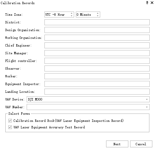
The operator adds the LiGeo project, control-point file and, if available, the KML or KMZ flight plan. Project information such as the UAV model, equipment serial number, engineer and time-zone offset is entered on the first page.
LiDAR360 can then prepare a Calibration Record, a Laser Accuracy Record, or both. The records bring the equipment information, calibration parameters and control-point results into a consistent report rather than leaving them across several project files.
Supported control targets can be detected automatically after the target type and physical size are entered. The current guide lists black-and-white squares, color squares and two- or three-layer concentric circles. Any target that is not recognized correctly can be selected manually in the point cloud window.
Open:
UAV LIDAR QC → Accuracy Check
This is a guided reporting workflow rather than a single accuracy calculation. After the LiGeo project and control-point table are added, the operator matches the ID, X, Y and Z columns, identifies the targets and assigns each point as an adjustment, check or strip check point.
LiDAR360 compares the measured positions with the known coordinates and prepares the selected tables. The report may include horizontal and vertical accuracy, inter-strip verification, trajectory statistics, flight-line records and control-point diagrams.
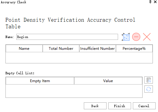
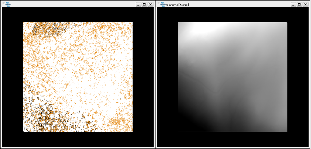
Point density can be tested inside the same workflow. Select Point Density, draw a representative area in the viewer and double-click to confirm it. LiDAR360 calculates the density and adds the selected area to the report.
Several local samples are more informative than one project-wide average. Particular attention should be given to flight-block edges, gaps between strips, steep slopes, areas beneath vegetation and locations affected by building occlusion
Once the point cloud has passed the required checks, processing can move to classification and product generation. For a terrain project, this normally means removing remaining outliers, classifying the ground and reviewing the result in Profile View before generating a DEM or DSM.
Terrain editing may still be required around bridges, retaining walls, water bodies and sudden changes in elevation. LiDAR360 can then produce contours, profiles, cross-sections, hydrological results and exports for GIS or engineering software, including LandXML/J-LandXML.
The final products should receive their own visual and numerical review. A point cloud can pass the control-point test while an incorrect ground classification or excessive surface smoothing removes important terrain features. Accuracy checking therefore continues through to the final DEM, contours or sections rather than ending with the initial QC report.
GNSS.ae is authorized to provide LiDAR360 training. Sessions can cover the complete workflow from project setup and point cloud inspection to strip alignment, classification, terrain generation, accuracy reporting and industry-specific analysis.
Training can also be organized around a company’s own datasets. This is particularly useful when operators need to select suitable parameters for local terrain, UAV sensors and project specifications rather than repeat a generic demonstration.
LiDAR360 is used to process, inspect and analyze LiDAR point clouds and imagery. Common applications include terrain mapping, UAV LiDAR quality control, forestry inventory, stockpile measurement, mining analysis, cross-section generation and 3D building modelling.
Yes. After ground points have been classified, the Terrain module can generate DEM and DSM products, edit terrain surfaces and create contour lines. V9 also supports automatic joining of fragmented contour sheets and export to several terrain formats.
Use UAV LIDAR QC → Accuracy Check. Import the LiGeo project and control-point table, identify the targets, assign point roles and review the horizontal, vertical, inter-strip and density results. LiDAR360 then creates the selected QC tables and report.
Use UAV LIDAR QC → Accuracy Check. Import the LiGeo project and control-point table, identify the targets, assign point roles and review the horizontal, vertical, inter-strip and density results. LiDAR360 then creates the selected QC tables and report.