One of the most common questions about ground penetrating radar (GPR) is how deep it can detect underground objects.
In real-world surveys, GPR penetration depth depends on several factors, including antenna frequency, soil properties, moisture, and the size of the target itself. Under favorable conditions, a low-frequency system can reach tens of meters below the surface, while in highly conductive soils, penetration may be limited to just a few tens of centimeters.
This article explains what affects GPR depth, how different antenna frequencies perform, and what you can realistically expect in both ground-based and drone-based surveys.
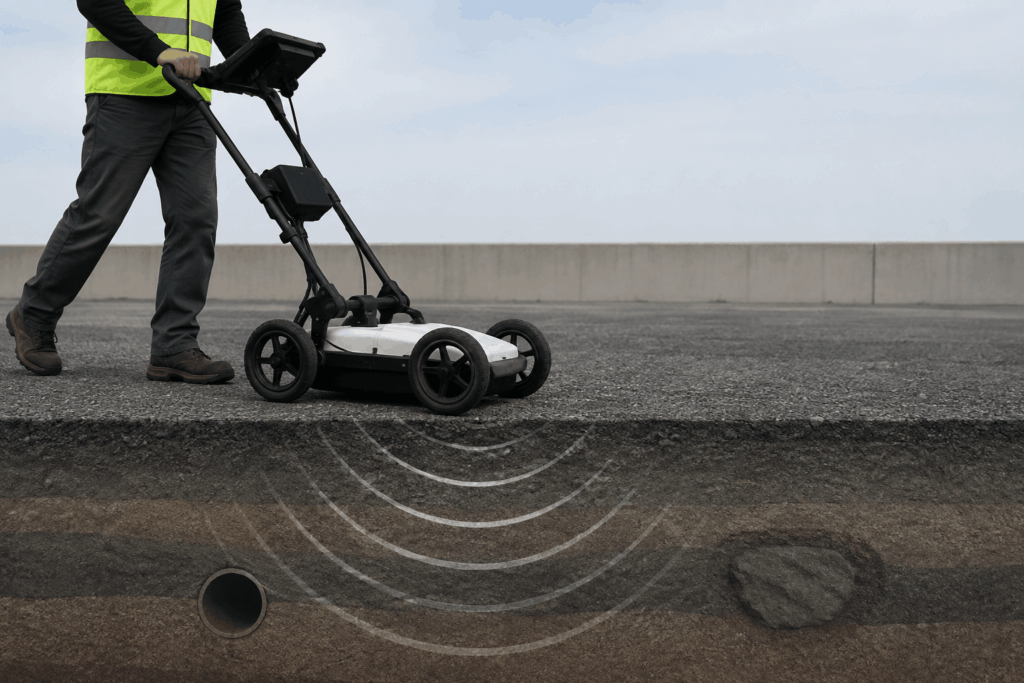
Ground penetrating radar transmits electromagnetic pulses into the ground and records the signals reflected from buried objects or changes in subsurface materials. The maximum detection depth depends on how much of that energy can travel through the ground before it becomes too weak to return a usable signal.
Several factors influence this process, and they all work together rather than independently.
The antenna frequency has the greatest influence on the balance between penetration depth and image resolution.
Lower-frequency antennas generate longer wavelengths that lose less energy while traveling through the ground. As a result, they can detect deeper geological structures, large voids, and glacier layers. The trade-off is lower resolution, making them less suitable for identifying small objects.
Higher-frequency antennas produce much finer detail but penetrate less deeply. They are commonly used for locating utilities, reinforcing bars, pavement layers, and other shallow features where accuracy matters more than depth.
Materials with low conductivity allow electromagnetic waves to travel much farther. Dry sand, gravel, granite, and ice are among the most favorable environments for radar surveys because they absorb very little signal.
Highly conductive materials behave differently. Clay-rich soils, saline ground, and seawater absorb radar energy quickly, often reducing penetration to less than one meter regardless of antenna frequency.
This is why identical GPR systems can deliver dramatically different results at different sites.
In many surveys, wet conditions reduce penetration depth, especially when clay is present. Even a relatively thin saturated clay layer near the surface can absorb much of the radar energy before it reaches deeper targets.
However, moisture is not always detrimental. Freshwater slows electromagnetic wave propagation, which can improve the separation between nearby underground features and produce clearer images. Saline water is much more problematic because its high conductivity rapidly attenuates the signal.
The object being surveyed also affects whether it can be detected.
Large objects reflect more radar energy than small ones and are generally easier to identify at greater depths. Flat, horizontal surfaces also produce stronger reflections than irregular or steeply inclined objects.
Material properties matter as well. Conductive targets such as metal pipes generate stronger reflections than non-conductive objects like plastic pipes. Nevertheless, plastic utilities can still be detected when survey conditions are favorable and the antenna frequency is appropriate.
The values below represent typical field performance in average soil with low conductivity and relatively low moisture content. Actual penetration can vary significantly depending on site conditions.
Ground-Based GPR Penetration
Central Frequency | Typical Depth | Smallest Detectable Target | Common Applications |
1 GHz | 0.3–1 m | 5–10 cm | Rebar mapping, thin ice layers, near-surface utilities |
600 MHz | 2–4 m | 10 cm | Utility mapping, shallow void detection, ice and snow thickness |
500 MHz | 2–4 m | 10 cm | Engineering surveys, utility detection, ice and snow thickness |
300 MHz | 4–12 m | 10–20 cm | Stratigraphy, bedrock profiling |
150 MHz | 8–25 m | 35–50 cm | Deep geological investigations, glaciology |
100 MHz | 15–80 m | 50–100 cm | Large underground voids, glaciers, deep dry sand |
50 MHz | Tens of meters in soil / hundreds of meters in ice | ~1 m | Deep glaciology, regional geological surveys |
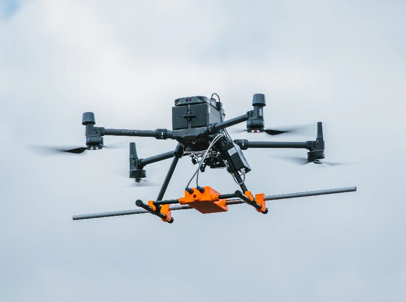
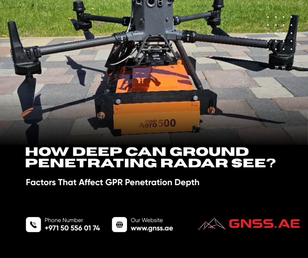
Drone-mounted GPR systems use the same radar principles as ground-based systems, but the antenna is positioned above the surface instead of directly on it.
Because part of the radar signal is reflected at the air-ground boundary before entering the subsurface, airborne systems generally achieve around half the penetration depth of an equivalent ground-based setup operating under the same conditions.
Central Frequency | Typical Depth from Drone | Maximum Antenna Height | Example GPR System |
1000 MHz | 0.3–0.5 m | 0.5 m | Zond Aero 1000 |
600/500 MHz | 1–2 m | 1.0 m | Zond Aero 600/500, MALÅ GeoDrone 600 |
300 MHz | 2–4 m | 1 m | Zond Aero LF |
150 MHz | 4–8 m | 2 m | Zond Aero LF |
100 MHz | 7–10 m | 3 m | Zond Aero LF |
Although drone-mounted systems sacrifice some penetration depth, they offer important operational advantages. They can safely survey unstable terrain, steep slopes, glaciers, contaminated sites, wetlands, and other areas that are difficult or hazardous to access on foot.
For the best data quality, the antenna should remain below the wavelength of the transmitted signal. For example, a 500 MHz antenna should typically fly no higher than about 60 cm above the ground, while a 100 MHz antenna can operate at heights of approximately 3 m. Maintaining a consistent altitude is one of the key factors affecting data quality, which is why accurate terrain-following capability is essential for drone-based GPR surveys.
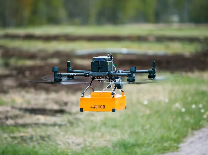
Unlike optical sensors, a GPR antenna cannot simply be flown higher to cover more ground. As the distance between the antenna and the surface increases, a larger portion of the radar signal is reflected at the air-ground interface instead of penetrating the subsurface. This reduces signal strength and limits the ability to detect buried objects.
Antenna Frequency | Recommended Maximum Flight Height |
1000 MHz | 0.5 m |
600/500 MHz | 1.0 m |
300 MHz | 1.0 m |
150 MHz | 2.0 m |
100 MHz | 3.0 m |
Flying above these heights can significantly reduce data quality, particularly over uneven terrain where the antenna-to-ground distance changes continuously.
For this reason, modern drone GPR surveys often rely on True Terrain Following (TTF). By automatically maintaining a consistent height above the surface, TTF helps improve signal consistency, increase target detectability, and reduce errors caused by varying flight altitude.
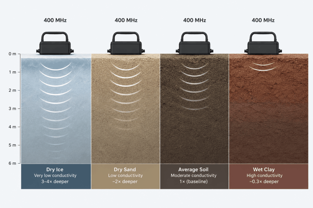
The penetration depths shown earlier represent average soil conditions. In reality, the geological environment can have an even greater impact on performance than the radar system itself.
Instead of treating every soil type separately, surveyors often use correction factors relative to average soil.
Ground Condition | Effect on GPR Signal | Approximate Multiplier |
Snow and ice (cold, fresh) | Nearly transparent to radar | 3–4× |
Dry sand, gravel, desert soils, peat | Very low conductivity | ~2× |
Average soil (ε ≈ 9) | Baseline | 1× |
Wet clay or silty loam | High conductivity, rapid signal absorption | ~0.3× |
Saturated soil after rainfall | Strong surface absorption | 0.2–0.5× |
Fertilized agricultural fields | Increased conductivity from dissolved salts | 0.3–0.7× |
Saline soil or seawater | Signal absorbed within centimeters | 0× |
The table highlights why two surveys using identical equipment can produce completely different results.
Dry, low-conductivity materials allow electromagnetic waves to travel much farther, making them ideal for deep investigations. Ice is one of the best environments for GPR because it absorbs very little radar energy, allowing low-frequency systems to detect features tens or even hundreds of meters below the surface.
At the opposite end of the spectrum are conductive materials such as wet clay and saline soils. In these environments, the radar signal weakens rapidly, often limiting penetration to less than one meter.
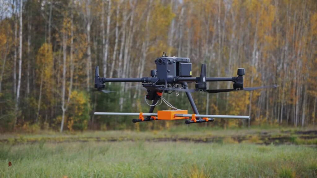
Estimating penetration depth before arriving on site helps reduce uncertainty and ensures the selected equipment matches the project requirements.
A practical workflow consists of five steps.
Key properties include soil composition, moisture content, and dielectric permittivity. These factors determine how quickly electromagnetic waves travel through the ground and how much energy is lost along the way.
Typical dielectric permittivity values include:
Material | Approximate Dielectric Permittivity (ε) |
Ice | ~3.2 |
Dry sand | ~4–6 |
Concrete | ~6–8 |
Average soil | ~9 |
Peat | ~30–80 |
Fresh water | ~80 |
Higher dielectric permittivity generally means slower wave propagation and greater signal attenuation.
Choose the highest antenna frequency capable of reaching the expected target depth.
Higher frequencies provide better resolution and make it easier to distinguish small underground objects. Lower frequencies sacrifice detail but offer significantly greater penetration.
Once the antenna frequency has been selected, adjust the expected penetration using the site conditions discussed earlier.
As a simple guideline:
During transmission, the antenna continues emitting energy while reflections from very shallow objects are already returning. As a result, targets located within this zone may not be detected clearly.
The dead zone becomes larger as antenna frequency decreases. Low-frequency systems designed for deep investigations may therefore miss shallow utilities or small near-surface features.
If the target is located close to the surface, using a higher-frequency antenna is often the better choice.
Before mobilizing equipment, it is good practice to verify that the selected antenna can achieve the required penetration and resolution under the expected site conditions.
Survey planning tools and GPR calculators can estimate expected penetration depth, target detectability, travel time, and blind zone characteristics based on antenna frequency, ground conditions, and flight height. While these estimates cannot replace field testing, they help reduce uncertainty and improve survey planning before work begins.
Several practices can significantly improve the accuracy of GPR surveys:
With proper site calibration, depth errors can often be reduced to only a few percent. Without calibration, an uncertainty of 15–30% should generally be expected, especially in heterogeneous soils.
There is no single answer to the question, “How deep can ground penetrating radar see?”
Penetration depth depends on a combination of antenna frequency, soil conductivity, moisture content, target characteristics, and survey methodology. In highly conductive soils, even a powerful system may only reach a few tens of centimeters. In dry sand, gravel, or glacier ice, low-frequency antennas can detect features tens of meters below the surface.
Choosing the right antenna is only part of the equation. Understanding local ground conditions, maintaining proper antenna height, and planning the survey carefully often have an even greater impact on the final results.
By matching the equipment to the site conditions and the project objectives, survey teams can achieve more reliable data, reduce uncertainty, and maximize the effectiveness of every GPR survey.
Ground penetrating radar can typically detect targets from 0.3 m to more than 30 m, depending on antenna frequency and ground conditions. In glacier surveys using low-frequency antennas, penetration may exceed 100 m.
The most important factors are antenna frequency, soil conductivity, moisture content, and the physical characteristics of the target. Highly conductive materials such as wet clay and saline soils reduce penetration significantly.
Yes. Moisture generally increases soil conductivity, causing the radar signal to lose energy more quickly. Saturated clay soils have one of the strongest negative effects on penetration depth.
For most utility surveys, 500–600 MHz antennas provide a good balance between penetration depth and resolution. Higher-frequency antennas may be used for very shallow utilities requiring greater detail.
Yes. Although plastic produces weaker reflections than metal, plastic pipes can still be detected when suitable antenna frequencies are used and soil conditions are favorable.
Not in terms of penetration depth. Drone-mounted systems typically reach about half the depth of equivalent ground-based systems. However, they provide major advantages in safety, survey speed, and access to difficult terrain.
Yes. Ground penetrating radar is widely used to inspect concrete structures, locate reinforcing bars, post-tension cables, embedded utilities, and detect internal voids or delamination.
GPR is generally not effective in saline soils, seawater, or highly conductive clay-rich environments, where radar signals are rapidly absorbed. In these conditions, alternative technologies such as sonar or electromagnetic methods may provide better results.