Mobile LiDAR is often seen as just one technology, but in reality, it represents a variety of distinct system architectures. These systems combine LiDAR sensors with positioning and motion estimation techniques like SLAM, GNSS, and IMU integration.
Handheld scanners, backpack systems, and UAV-based LiDAR platforms aren’t just different models of the same tool; each one offers a unique way to tackle the challenge of reconstructing geometry while keeping a dependable trajectory estimate.
Therefore, choosing a mobile LiDAR system is not about comparing features. It is about understanding how it is going to perform in the context of real-world limitations (signal attenuation, low-visibility, long-duration trajectories).

Handheld systems are typically used for indoor environments, confined spaces, and short-range scanning tasks. Their main advantage is flexibility: the operator can move freely and capture data in areas that are inaccessible to larger systems.
To such systems belong handheld SLAM-based solutions such as:
However, can also lead to some inconsistencies, as the path is directly related to the operator’s motion, which can cause significant variation in scan geometry. Range is also limited, reducing effectiveness in large environments.

Backpack systems extend the capabilities of handheld scanners by offering a more stable platform and allowing for longer scanning sessions. They are commonly used in tunnels, warehouses, mines, and large indoor or mixed environments.
These systems (e.g. South RobotSLAM Handheld 3D Laser Scanner 32 Channels, 640,000 pts/sec included with backpack) typically combine LiDAR with IMU and, where possible, GNSS. This enhances the trajectory estimation relative to handheld systems; but the fundamental limitation is the same: SLAM drift. Over long distances, especially in areas with limited geometric variation (corridors or tunnels) positional error accumulates. If there’s no reliable loop closure or external correction, this drift can cause misalignment in the dataset.

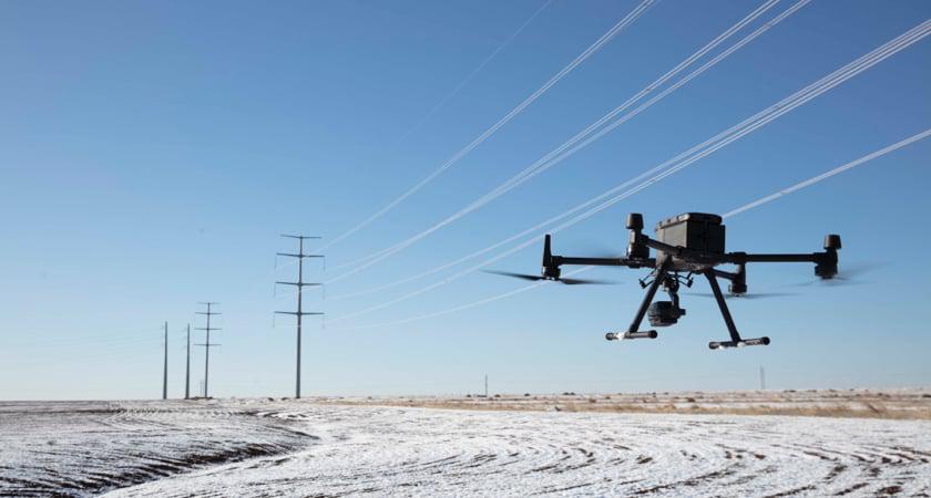
UAV-based LiDAR systems, for example, DJI Matrice 400 + Zenmuse L3 LiDAR Payload, operate under a different set of assumptions. They are designed for large-area mapping, corridor surveys, and vegetation penetration, where aerial coverage provides a clear advantage.
Unlike ground-based systems, UAV LiDAR relies heavily on GNSS and IMU for trajectory estimation. This allows for consistent large-scale mapping, but introduces dependence on signal quality.
In open environments, UAV LiDAR delivers high consistency and coverage. In constrained environments—such as dense urban areas or near large structures—GNSS degradation can directly affect trajectory accuracy.
From a workflow perspective, UAV LiDAR is most suitable for:
Some more combinations of UAV-bases LiDAR systems:
More detailed analysis of how the Zenmuse L3 is applied in real LiDAR workflows — and how it combines LiDAR efficiency with photogrammetry-grade imaging within a single optimized flight mission we covered in one of our previous articles: Can Zenmuse L3 Combine LiDAR Efficiency with Photogrammetry-Grade Imaging in a Single Flight?
Parameter | Handheld LiDAR | Backpack LiDAR | UAV LiDAR |
Primary positioning method | SLAM (LiDAR + IMU) | SLAM + IMU (+ optional GNSS) | GNSS + IMU (+ LiDAR) |
Trajectory stability | Low (operator-dependent) | Medium (more stable motion) | High (controlled flight path) |
Main error source | Motion inconsistency + short-range SLAM drift | Long-duration SLAM drift | GNSS degradation (multipath, signal loss) |
Typical range | Short | Medium | Long |
Coverage efficiency | Low | Medium | High |
Absolute positioning capability | No (relative only) | Limited (if GNSS available) | Yes (GNSS-based) |
Performance in GNSS-denied environments | High | High | Low |
Performance in large-scale environments | Low | Medium | High |
Sensitivity to environment geometry | High (needs features) | High (needs features for SLAM) | Medium (depends on GNSS + terrain) |
Best use cases | Indoor mapping, confined spaces | Tunnels, mines, warehouses | Corridors, vegetation, large areas |
Key limitation | Operator-induced instability | Accumulated drift over long paths | Dependence on GNSS quality |

SLAM (Simultaneous Localization and Mapping) is a computational positioning and mapping method used in mobile LiDAR systems when external GNSS signals are unavailable or unreliable. Rather than use external positioning, SLAM estimates the sensor’s trajectory by continuously combining two data streams: LiDAR geometry measurements and inertial (IMU) motion data.
In simple terms, SLAM allows the system to “understand where it is” by analyzing how the surrounding environment changes as the sensor moves, while simultaneously building a map of that environment.
While this approach enables fully autonomous scanning without external positioning infrastructure, it introduces a fundamental limitation: error accumulation over time.
Since SLAM continuously estimates its position based on previous measurements instead of a fixed global reference, even tiny inaccuracies in motion estimation can gradually add up along the path. In real-world applications, this SLAM drift usually increases at a rate of about 1 to 3 centimeters for every 10 meters traveled, influenced by factors like feature density, sensor quality, and the presence of loop closure events.
In long, straight environments like hallways, tunnels, or underground passages, this drift can lead to misalignments of decimeters to meters over longer scanning distances.
Loop closure can somewhat compensate for this drift by aligning previously visited locations, but without loops or with featureless or repetitive environments (e.g. pipe walls), loop closures are unavailable and drift remains uncorrected.
It is a common misconception that more points always result in better output. Density and accuracy are independent parameters. A system can output a dense point cloud with a systematic mis-registration, caused by trajectory error. In this case, increasing the number of points only increases the volume of incorrect data. Practical effects include warped geometry in structural models, registration errors between scan segments and lower utility in engineering workflows.
Accuracy depends on the quality of trajectory estimation, not just the number of points captured. This is particularly important in SLAM-based systems, where trajectory error propagates into every point.
The effectiveness of a LiDAR system depends on how its scanning characteristics match the environment.
Short range sensors, such as those found in handheld systems, are most effective in small spaces and are less effective in larger areas. Long range sensors, which are used in UAV systems, allow larger areas to be scanned quickly but reduce the level of detail that can be obtained at distance.
Scan pattern also plays a critical role. Rotary LiDAR scanners produce a complete 360-degree scan which can help stability in the SLAM. However, coverage alone does not guarantee accuracy if the environment lacks distinct features.
In environments with:
scan pattern must be considered together with SLAM robustness and trajectory control.
Mobile LiDAR systems can operate in two fundamentally different modes:
Without GNSS, the system produces internally consistent geometry but lacks global reference. With GNSS integration, the dataset can be georeferenced and aligned with external coordinate systems.
However, GNSS availability is environment-dependent. It is typically unavailable or unreliable in:
In these scenarios, IMU and LiDAR-based estimation become the primary sources of positioning, and absolute accuracy must be recovered through control points or post-processing.
The performance of a mobile LiDAR system is not determined solely by hardware. Processing workflow plays a critical role in the final data quality.
Key workflow stages include:
In large projects, data volumes can reach hundreds of gigabytes, making processing time and software capability a limiting factor.
In many cases, improving workflow efficiency has a greater impact on project outcomes than incremental hardware improvements.
The most important factor in selecting a mobile LiDAR system is not specification, but environment.
Different environments impose fundamentally different constraints on positioning stability, trajectory reconstruction, and sensor performance. As a result, system selection is primarily driven by error behavior rather than hardware capability:
Handheld or backpack systems with SLAM-based positioning like South RobotSLAM Lite Handheld 3D Laser Scanner


Choosing a mobile LiDAR scanner is not a question of selecting the most advanced device. It is a matter of aligning system architecture with environmental constraints and workflow requirements.
The key challenges—SLAM drift, GNSS degradation, trajectory instability, and processing complexity—are not isolated issues. They are interconnected factors that define the reliability of the entire mapping process.
In practical terms, successful deployment depends on:
In mobile LiDAR mapping, accuracy is not determined by the sensor alone. It is the result of how well the system maintains stability under real-world conditions.